
Description
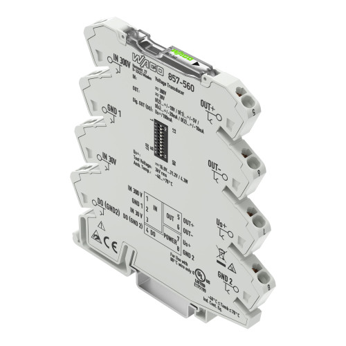
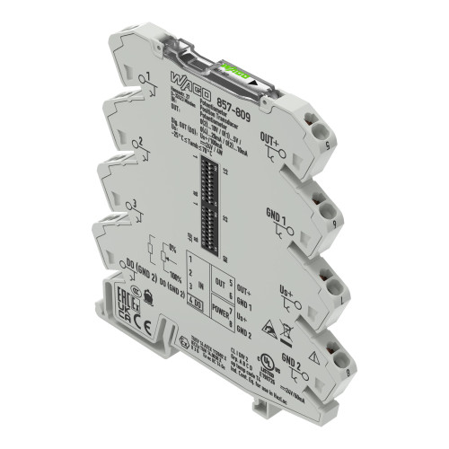
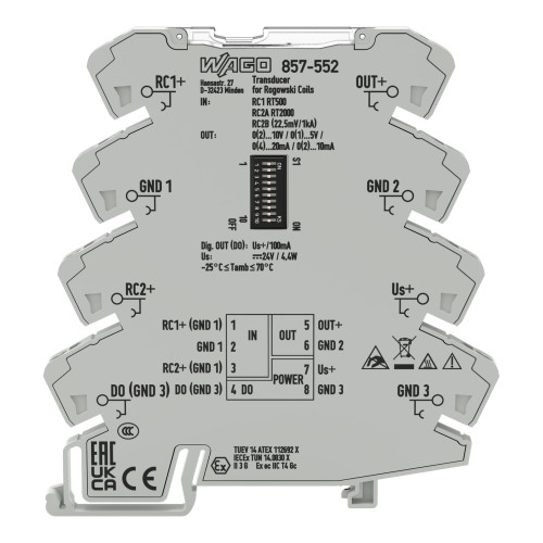
The WAGO 857-569 jUMPFLEX® signal conditioner features power, configurable, with digital output.
Specifications
- Configuration options: DIP switch; WAGO Interface Configuration Software
- Input signal type: Voltage; Current
- Input signal (voltage): 300 V AC/DC (IN 1)
- Input signal (current): 0 … 5 A AC/DC (IN 2)
- Measurement frequency: 15 … 70 Hz (AC)
- Frequency range: 15 … 70 Hz (AC)
- Input resistance (current input): ≤ 10 mΩ
- Input resistance (voltage input): ≥ 300 kΩ
- Input current (max.): 10 A AC/DC (IN 2; permanent)
- Input voltage (max.): 600 V (IN 1; permanent)
- Response threshold: 300 mV (IN 1); 10 mA (IN 2)
- Resolution (voltage): 30 mV (IN 1)
- Resolution (current): 1 mA (IN 2)
- Output signal type: Current; Voltage
- Output signal (voltage): 0 … 5 V; 1 … 5 V; 0 … 10 V; 2 … 10 V (invertible, also bipolar)
- Output signal (current): 0 … 10 mA; 2 … 10 mA; 0 … 20 mA; 4 … 20 mA (invertable, also bipolar)
- Load impedance (voltage output): ≥ 1 kΩ
- Load impedance (current output): ≤ 600 Ω
- Switching voltage (DO) max.: Supply voltage applied
- Continuous current (DO) max.: 100 mA (no internal restriction)
- Number of switching thresholds (DO): 1 or 2 (adjustable)
- Configurable rise/fall delay time (DO): 0 … 60 s (via software)
- Measurement method: RMS measurement; Arithmetic mean value
- Limit frequency: 2 kHz
- Software filter (adjustable): Moving average value (filter level: 30)
- Step response (typ.): 100 ms
- Transmission error (max.): ≤ 0.5 % (of the full scale value)
- Temperature coefficient: ≤ 0.01 %/K
- Power supply type: 24 VDC
- Nominal supply voltage US: 24 VDC
- Supply voltage range: ±30 %
- Current consumption at nominal supply voltage: ≤ 46 mA (+ IDO)
- Rated Voltage: 300 V; 150 V (UL)
- Measurement category per EN/UL 61010-2-030: CAT II (input)
- Note on insulation parameters: Danger: Configuration via the service interface must only be performed with a voltage-free measurement input! The digital output (DO) operates at the supply potential.
- protection rating: IP20
- Test voltage (input/analog output/supply/service interface): 2.5 kVAC; 50 … 60 Hz; 1 min
- Overvoltage category: II
- Pollution degree: 2
- Insulation type (input/analog output/supply/service interface): Reinforced insulation (safe isolation)
- Insulation type (input/analog output/supply/service interface): Double insulation (impedance and basic insulation);; Requirement: The GND 1 input must not become hazardous when active and the measurement is performed as a low-side measurement!
- Connection Data — Connection technology: Push-in CAGE CLAMP®
- Connection Data — Solid conductor: 0.08 … 2.5 mm² / 28 … 14 AWG
- Connection Data — Fine-stranded conductor: 0.34 … 2.5 mm² / 22 … 14 AWG
- Connection Data — Strip length: 9 … 10 mm / 0.35 … 0.39 inches
- Width: 6 mm / 0.236 inches
- Height: 94 mm / 3.701 inches
- Depth from upper-edge of DIN-rail: 97.8 mm / 3.85 inches
- Mounting type: DIN-35 rail
- Insulation material (main housing): Polyamide (PA66)
- Flammability class per UL94: V0
- Weight: 34 g
- Ambient temperature (operation): -40 … +70 °C (at nominal current)
- Ambient temperature (storage): -40 … +85 °C
- Temperature range of connection cable: ≥ (Tambient + 10 K)
- Temperature range of the connection cable (UL): 80 °C
- Relative humidity: 5 … 95 % (no condensation permissible)
- Operating altitude (max.): 2000 m
- Conformity marking: CE
- EMC immunity to interference: EN 61000-6-2; EN 61326-2-3; EN 50121-3-2
- EMC emission of interference: EN 61000-6-3; EN 61326-2-3; EN 50121-3-2
- Standards/specifications: EN 61010-1; EN 61373; EN 50121-3-2
Image shown is representative. Refer to the product specifications for the exact configuration.