
Description
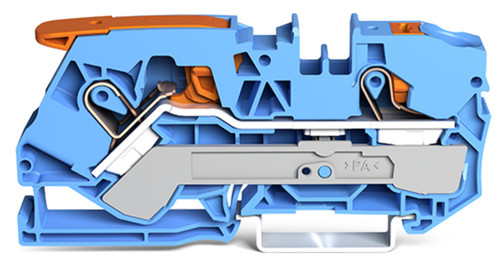
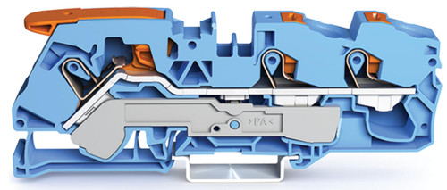
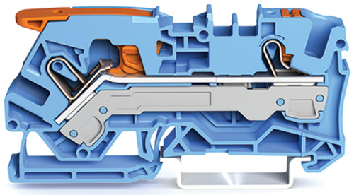
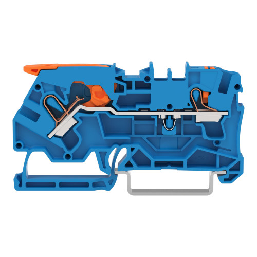
The WAGO 2116-5204 tOPJOB®S feedthrough terminal block with Lever and Push-button features rail mount, 2-conductor, 10 mm wide, blue.
Specifications
- IEC Approvals — Ratings per: IEC/EN 60947-7-1
- IEC Approvals — Rated voltage (III / 3): 800 V
- IEC Approvals — Rated impulse withstand voltage (III / 3): 8 kV
- IEC Approvals — Rated current: 76 A
- IEC Approvals — Current at conductor cross-section (max.) mm²: 90 A
- IEC Approvals — Legend (ratings): (III / 3) ≙ Overvoltage category III / Pollution degree 3
- Ratings per IEC/EN – Notes — Rated current (note): 15 mm high DIN-35 rails shall be used for a current load higher than 76 A!
- UL Approvals — Approvals per: UL 1059
- UL Approvals — Rated voltage UL (Use Group B): 600 V
- UL Approvals — Rated current UL (Use Group B): 85 A
- UL Approvals — Rated voltage UL (Use Group C): 600 V
- UL Approvals — Rated current UL (Use Group C): 85 A
- Approvals per: CSA 22.2 No 158
- Rated voltage CSA (Use Group B): 600 V
- Rated current CSA (Use Group B): 85 A
- Rated voltage CSA (Use Group C): 600 V
- Rated current CSA (Use Group C): 85 A
- Reference to hazardous areas: See “Downloads – Documentation – Additional Information: Technical Section; Technical Explications”
- Ratings per: ATEX: PTB 18 ATEX 1012 U / IECEx: PTB 18.0019U (Ex eb IIC Gb)
- Rated voltage EN (Ex e II): 550 V
- Rated current (Ex e II): 76 A
- Rated current (Ex e II) with jumper: 65 A
- Power loss, per pole (potential): 2.426 W
- Rated current IN for power loss specification: 76 A
- Resistance value for specified, current-dependent power loss: 0 Ω
- General information — Wiring direction: Front-entry wiring
- Connection Data — Clamping units: 2
- Connection Data — Total number of potentials: 1
- Connection Data — Number of levels: 1
- Connection Data — Number of jumper slots: 2
- Connection 1 — Connection technology: Push-in CAGE CLAMP®
- Connection 1 — Actuation Method: Lever
- Connection 1 — Connectable conductor materials: Copper
- Connection 1 — Nominal cross-section: 16 mm²
- Connection 1 — Solid conductor: 0.5 … 16 mm² / 20 … 6 AWG
- Connection 1 — Solid conductor; push-in termination: 2.5 … 16 mm² / 14 … 6 AWG
- Connection 1 — Stranded conductor: 0.5 … 25 mm² / 20 … 4 AWG
- Connection 1 — Fine-stranded conductor: 0.5 … 25 mm² / 20 … 4 AWG
- Connection 1 — Fine-stranded conductor; with insulated ferrule: 0.5 … 16 mm² / 20 … 6 AWG
- Connection 1 — Fine-stranded conductor; with ferrule; push-in termination: 6 … 16 mm² / 10 … 6 AWG
- Connection 1 — Note (conductor cross-section): Depending on the conductor characteristic, a conductor with a smaller cross-section can also be inserted via push-in termination. ; AWG specifications were converted according to IEC.
- Connection 1 — Strip length: 18 … 20 mm / 0.71 … 0.79 inches
- Connection 1 — Wiring direction: Front-entry wiring
- Connection 2 — Actuation type: Push-button
- Width: 12 mm / 0.472 inches
- Height: 91.5 mm / 3.602 inches
- Depth from upper-edge of DIN-rail: 37.1 mm / 1.461 inches
- Depth: 45.2 mm / 1.78 inches
- Mounting type: DIN-35 rail
- Marking level: Center/side marking
- Color: blue
- Insulation material (main housing): Polyamide (PA66)
- Flammability class per UL94: V0
- Actuator color: orange
- Weight: 33.1 g
- Processing temperature: -35 … +85 °C
- Continuous operating temperature: -60 … +105 °C
Image shown is representative. Refer to the product specifications for the exact configuration.