
Description
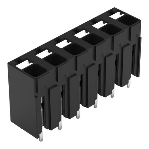
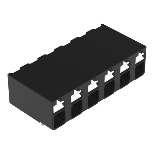
The WAGO 2086-3126 tHR PCB terminal block features push-button, 1.5 mm², Pin spacing 5 mm, 6-pole, Push-in CAGE CLAMP®, Solder pin length 2.4mm, black.
Specifications
- IEC Approvals — Ratings per: IEC/EN 60664-1
- IEC Approvals — Rated voltage (III / 3): 500V
- IEC Approvals — Rated impulse withstand voltage (III / 3): 6kV
- IEC Approvals — Rated voltage (III/2): 630V
- IEC Approvals — Rated impulse withstand voltage (III/2): 6kV
- IEC Approvals — Nominal voltage (II/2): 1000V
- IEC Approvals — Rated impulse withstand voltage (II/2): 6kV
- IEC Approvals — Rated current: 17.5A
- IEC Approvals — Legend (ratings): (III / 2) ≙ Overvoltage category III / Pollution degree 2
- UL Approvals — Approvals per: UL 1059
- UL Approvals — Rated voltage UL (Use Group B): 300V
- UL Approvals — Rated current UL (Use Group B): 14A
- UL Approvals — Rated voltage UL (Use Group D): 300V
- UL Approvals — Rated current UL (Use Group D): 10A
- Approvals per: CSA
- Rated voltage CSA (Use Group B): 300V
- Rated current CSA (Use Group B): 14A
- Rated voltage CSA (Use Group D): 300V
- Rated current CSA (Use Group D): 14A
- Connection Data — Clamping units: 6
- Connection Data — Total number of potentials: 6
- Connection Data — Number of connection types: 1
- Connection Data — Number of levels: 1
- Connection 1 — Connection technology: Push-in CAGE CLAMP®
- Connection 1 — Actuation Method: Push-button
- Connection 1 — Solid conductor: 0.14 … 1.5 mm² / 28 … 16 AWG
- Connection 1 — Fine-stranded conductor: 0.14 … 1.5 mm² / 26 … 14 AWG
- Connection 1 — Fine-stranded conductor; with insulated ferrule: 0.25 … 0.75 mm²
- Connection 1 — Fine-stranded conductor; with uninsulated ferrule: 0.25 … 1.5 mm²
- Connection 1 — Strip length: 8 … 9 mm / 0.31 … 0.35 inches
- Connection 1 — Conductor connection direction to PCB: 90°
- Connection 1 — Number of poles: 6
- Pin spacing: 5 mm / 0.197 inches
- Width: 29.2 mm / 1.15 inches
- Height: 16 mm / 0.63 inches
- Height from the surface: 13.6 mm / 0.535 inches
- Depth: 7.8 mm / 0.307 inches
- Solder pin length: 2.4mm
- Solder pin dimensions: 0.3 x 0.8 mm
- Plated through-hole diameter (THR): 1 (+0.1) mm
- PCB contact: THR
- Solder pin arrangement: over the entire terminal strip (staggered)
- Number of solder pins per potential: 1
- Color: black
- Insulation material (main housing): Polyphthalamide (PPA GF)
- Flammability class per UL94: V0
- Contact material: Electrolytic copper (ECu)
- Weight: 3.6g
- MSL per J-STD 020D: 1
- Limit temperature range: -60 … +105 °C
- Ambient temperature (installation): -35 … +60 °C
- Processing temperature: -35 … +60 °C
- Continuous operating temperature: -60 … +105 °C
Installation: Supply with WAGO installation instructions and follow the manufacturer’s technical ratings and installation requirements.